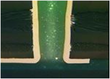
In today’s world almost all printed circuit boards are assembled using surface mount components. These components are used because in higher volumes the process is automated as the components are picked out by a gantry robot at high speed and placed into solder paste. This solder paste is melted or reflowed thereby establishing the electrical connection between the components and the PCB. In addition, this connection mechanically affixes the component to the PCB to create a reliable interconnection. If there are high voltage connections or connectors around the periphery of the board, the devices need to be attached the PCB using a different process than previously-described. These through-hole parts are soldered by molten solder contacting the inserted parts leads or legs and running up through a plated hole in the PCB. This process is known as a wave or selective soldering. These connectors, high voltage or other through-hole (Figure 1) parts can be formed and placed into the holes by hand. They are then attached via a hand soldering operation with a soldering iron.
Hand soldering of through-hole connectors and other components may be an option in certain circumstances for the initial build of a printed circuit board. One of the cases where hand soldering may be the best option is when the quantity of boards, like in a prototype production run, is small. This means hand soldering may be the fastest and least expensive way to get the few boards for testing into the hands of the customer. In other cases, where the leads of the component are formed or bent into special configurations, this may only be accomplished with a trained soldering technician being able to form the leads and properly solder the connections. If the PCB has wire terminations on it that need to be attached with solder, in many cases only hand soldering of the electronics can accomplish this.
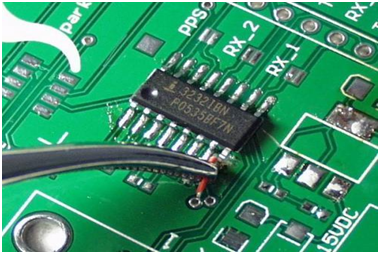
Hand soldering on printed circuit boards may also occur when there are designs of the circuit board either through error or “feature enhancement” which require jumper wires between electrical connections. These jumper wires make an electrical connection with a small piece of insulated wire instead of the traces of copper which form the electrical interconnection on printed circuit boards. A shown in Figure 2 below these wires are typically hand soldered as they cannot be run through automated machinery in this format. These wires are usually stripped, tinned and then hand soldered in to place.
Fig 2 –Jump Wires are Hand Soldered on Printed Circuit Boards
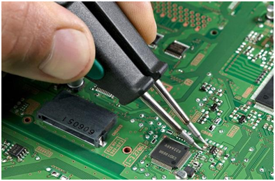
Another operation for hand soldering on printed circuit boards is PCB rework. In PCB rework the initial integrity of the PCB is restored when a component is replaced with a new component. (Figure 3). The hand soldering technician or PCB rework technician uses hand soldering skills to remove the component, prepare and clean the removed location and then hand solder s replacement component into place. After cleaning the site is inspected per the latest inspection criteria.
Fig 3. PCB rework , another form of hand soldering on a PCB
If you require professional hand soldering services then make sure your outsourced partner has both the right soldering tools, the right personnel with the right credentials and processes in place in order to perform the work at hand. For professional hand soldering skills make sure your potential outsourcing partner has the right soldering tools. The outsourced service provider should have and be familiar with a wide range of soldering irons and soldering iron tips. For example for hand soldering of RF shields BEST has worked with a major soldering equipment vendor in order to design and test a soldering tip for the complete soldering or dif BEST follows industry best manufacturing practices when it comes to handling your product. We not only teach the J-STD-001 standard for electronics assembly but we follow it when hand soldering your boards. We also follow the IPC-A-610 inspection guidelines for the assembly (yes, we teach that as well). What this means is that we foll...
The IPC J-STD-001 certification training requires the use of several consumable materials including fluxes and solders, a PCB cleaning agent, wipes as well as the J-STD-001 soldering training kit . Whether it is certification training done at the CIT or CIS level, J-STD-001 certification training requires these consumables as well as other pieces of equipment for hand soldering including but certainly not limited to a soldering iron, inspection equipment, soldering tips, wire cutters, orangewood sticks, and needle nose pliers. In addition to the above, each student should have to their avail the J-STD-001 “Requirements for Soldered Electrical and Electronic Assemblies” There are numerous components required as part of the J-STD-001 solder training kit. Below you will find the materials typically found in a J-STD-001 soldering kit: PCBs with a lead-free compatible surface finish 1/4 Watt Axial Resistors T05 Transistors Transistor Standoffs Axial Diodes CKO6 Capacitors Ca...


Comments
Post a Comment